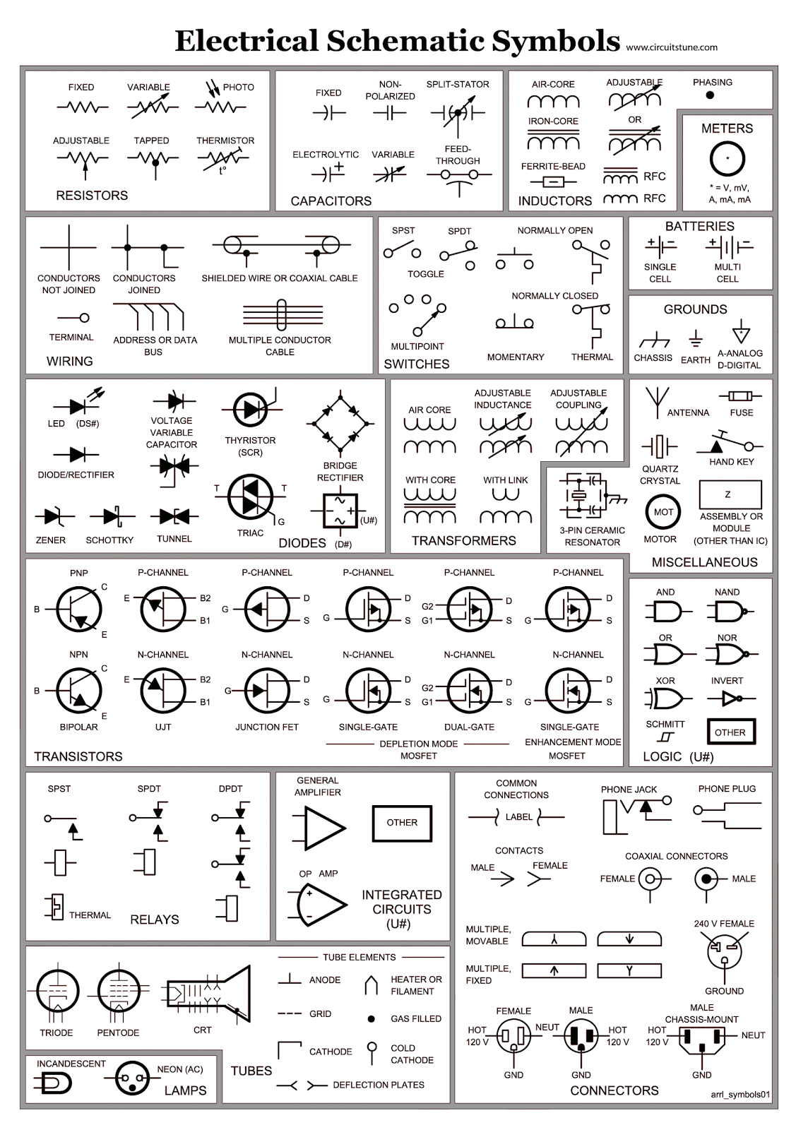
Wiring Schematics Symbols are crucial for understanding and interpreting electrical diagrams. These symbols are used to represent various components and connections in a circuit diagram, making it easier for technicians to analyze and troubleshoot electrical systems.
Why Wiring Schematics Symbols are essential
- Provide a visual representation of complex electrical systems
- Standardize the communication of electrical designs
- Help technicians identify components and connections quickly
- Aid in troubleshooting and diagnosing electrical issues
Reading and interpreting Wiring Schematics Symbols
When reading a wiring diagram, it is important to familiarize yourself with common symbols used in electrical schematics. Some key symbols include:
- Resistor: Represents resistance in a circuit
- Capacitor: Stores electrical charge
- Diode: Allows current to flow in one direction
- Ground: Connection to earth or a common ground point
Using Wiring Schematics Symbols for troubleshooting
Wiring diagrams play a crucial role in diagnosing electrical problems. By following the flow of current through the circuit and identifying components using symbols, technicians can pinpoint issues such as short circuits, open circuits, or faulty components.
Safety when working with electrical systems
It is essential to prioritize safety when working with electrical systems and using wiring diagrams. Some safety tips include:
- Always turn off power before working on electrical circuits
- Use insulated tools to prevent electric shock
- Follow proper lockout/tagout procedures when working on live circuits
- Wear appropriate personal protective equipment, such as gloves and safety goggles
Wiring Schematics Symbols
Basic Electrical Wiring Diagram Symbols

Electrical Schematic Symbols ~ CircuitsTune

All Electrical Schematic Symbols

Basic Wiring Diagram Symbols
.jpg)
Common Schematic Symbols Used In Circuit Diagrams
How To Read Electrical Schematic Symbols
