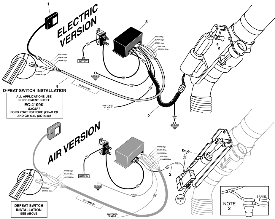
Brake Motor Wiring Diagrams are essential tools for anyone working on electrical systems in vehicles or machinery. These diagrams provide a detailed illustration of how the brake motor’s wiring is configured, helping mechanics troubleshoot issues, make repairs, and ensure proper functioning of the system.
Importance of Brake Motor Wiring Diagrams
Brake Motor Wiring Diagrams are essential for the following reasons:
- They help identify the different components of the brake motor system.
- They show the connections between various components, such as the brake, motor, and power source.
- They provide a clear understanding of the electrical circuit, ensuring proper installation and maintenance.
Reading and Interpreting Brake Motor Wiring Diagrams
When reading a Brake Motor Wiring Diagram, it is important to pay attention to the following:
- Identify the symbols and colors used in the diagram to represent different components.
- Follow the flow of the circuit, starting from the power source and ending at the brake motor.
- Check for any labels or annotations that provide additional information about the wiring connections.
Using Brake Motor Wiring Diagrams for Troubleshooting
Brake Motor Wiring Diagrams are invaluable for troubleshooting electrical problems, as they help mechanics:
- Identify the root cause of an issue by tracing the wiring connections.
- Check for continuity and voltage at various points in the circuit to pinpoint the fault.
- Compare the actual wiring with the diagram to ensure that all connections are correct.
Safety Tips for Working with Brake Motor Wiring Diagrams
When working with electrical systems and using Brake Motor Wiring Diagrams, it is crucial to prioritize safety. Here are some safety tips and best practices:
- Always disconnect the power source before working on the wiring to prevent electrical shock.
- Use insulated tools and wear appropriate personal protective equipment (PPE) when handling electrical components.
- Double-check your work and ensure all connections are secure before energizing the system.
Brake Motor Wiring Diagram
Engine Brake Wiring Diagram – Wiring Diagram and Schematics

Clutch Brake Motor Connection Diagram Rectifier Module – YouTube

Motor brake rectifier connection diagram | Engineers CommonRoom

Engine Brake Wiring Diagram – Wiring Diagram and Schematics
