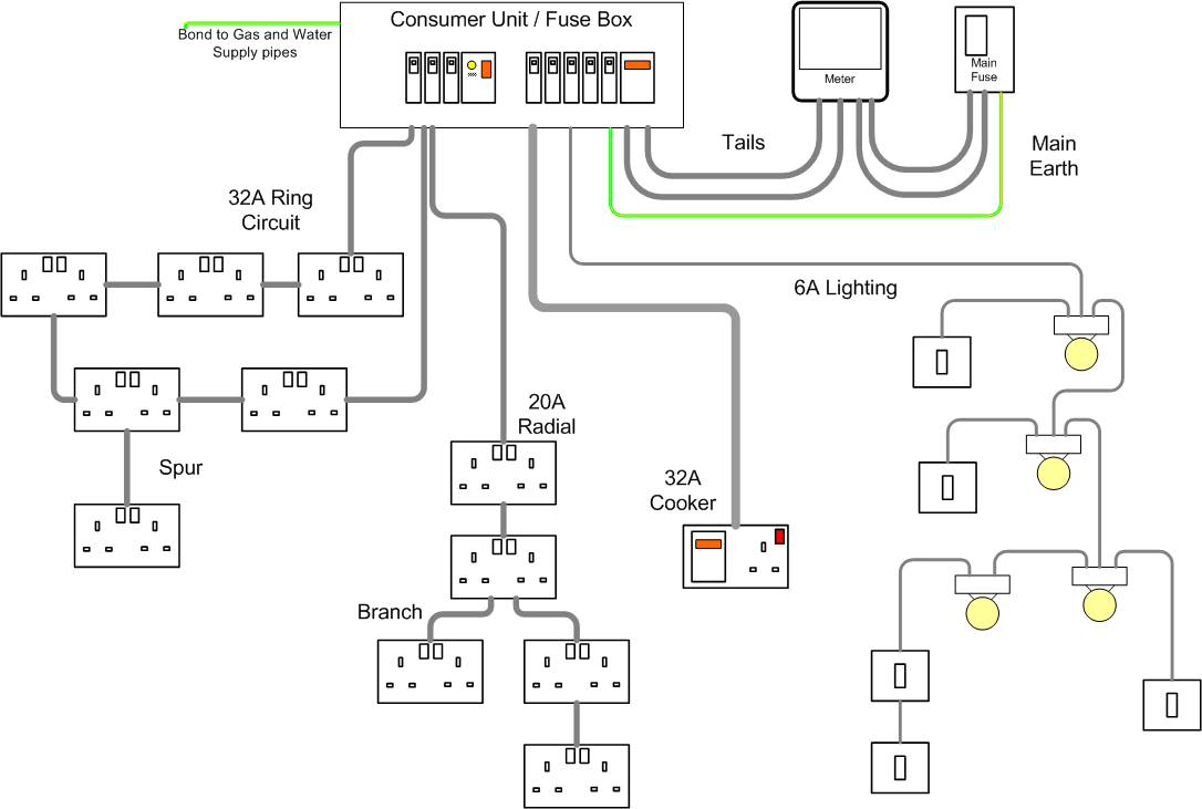
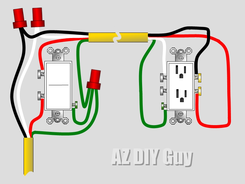
Basic Electrical Outlet Wiring Diagrams are essential tools for anyone working with electrical systems or attempting to understand how electrical outlets are wired in a building. These diagrams provide a visual representation of the wiring configuration for electrical outlets, helping users to identify the different components and connections involved in the electrical circuit.
Importance of Basic Electrical Outlet Wiring Diagrams
- Ensure proper installation of electrical outlets
- Prevent electrical hazards and malfunctions
- Understand the electrical layout of a building
- Help with troubleshooting electrical problems
- Comply with electrical codes and regulations
Reading and Interpreting Basic Electrical Outlet Wiring Diagrams
When interpreting a Basic Electrical Outlet Wiring Diagram, it is important to understand the symbols and abbreviations used in the diagram. Here are some key points to consider:
- Identify the different components such as outlets, switches, wires, and connections
- Follow the flow of the electrical current from the power source to the outlet
- Understand the color-coding of wires and their corresponding functions
- Pay attention to any labels or notes provided in the diagram
Using Basic Electrical Outlet Wiring Diagrams for Troubleshooting
Basic Electrical Outlet Wiring Diagrams can be valuable tools for troubleshooting electrical problems. By following the wiring diagram, users can easily trace the path of the electrical circuit and identify potential issues such as loose connections, faulty components, or incorrect wiring configurations.
Safety Tips for Working with Electrical Systems
- Always turn off the power supply before working on electrical systems
- Use insulated tools to prevent electrical shocks
- Wear appropriate personal protective equipment such as gloves and safety goggles
- Avoid overloading electrical circuits
- Consult a professional electrician if unsure about any electrical work
Basic Electrical Outlet Wiring Diagram
Basic Electrical Outlet Wiring Diagram

Beginner Basic Electrical Outlet Wiring Diagram

How To Install An Outlet On A Circuit – Circuit Diagram
/wiring-electrical-receptacle-circuits-through-a-receptacle-1152787-01-2a9a43dca2d04d6597dcfb791a548ff9.jpg?strip=all)
Electrical Outlet Wiring 3 Wires

Basic Electrical Outlet Wiring Diagram – Printable Form, Templates and

Basic Electrical Outlet Wiring Diagram
