Opening paragraph:
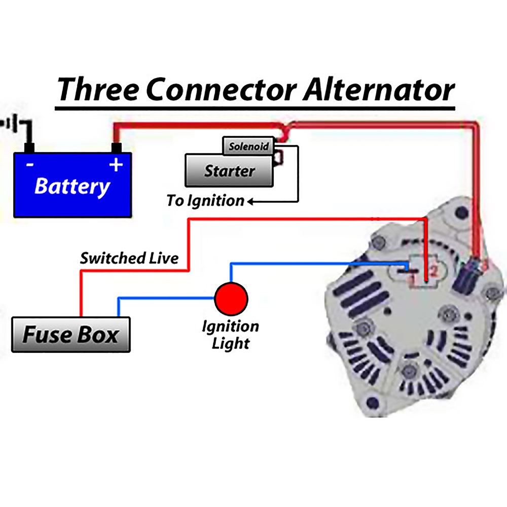
An alternator wiring schematic is a diagram that shows the connections and layout of the electrical components in a vehicle’s alternator system. Understanding how to read and interpret these schematics is essential for any mechanic or DIY enthusiast working on automotive electrical systems.
Why are Alternator Wiring Schematic essential?
- Helps identify the various components of the alternator system
- Guides in diagnosing and troubleshooting electrical issues
- Aids in understanding the flow of electricity within the system
- Ensures proper installation and connection of components
How to read and interpret Alternator Wiring Schematic effectively
- Start by familiarizing yourself with the symbols and colors used in the schematic
- Identify the key components such as the alternator, battery, voltage regulator, and wiring connections
- Follow the flow of electricity from the battery to the alternator and other components
- Pay attention to the direction of current flow and the voltage levels at different points in the system
Using Alternator Wiring Schematic for troubleshooting electrical problems
- Trace the wiring diagram to locate any loose connections or damaged wires
- Check for continuity and proper voltage levels at various points in the system
- Compare the actual wiring with the schematic to identify any discrepancies
- Use the schematic to determine the correct sequence for testing components in the system
Importance of safety when working with electrical systems
When working with alternator wiring schematics or any electrical system, safety should always be a top priority. Here are some tips to ensure your safety:
- Disconnect the battery before working on the electrical system
- Avoid working on the system when the engine is running
- Use insulated tools to prevent electrical shocks
- Always wear safety goggles and gloves when handling electrical components
- If you are unsure about a particular wiring diagram or electrical issue, seek professional help
Alternator Wiring Schematic
Common Delco SI Series Alternator Wiring Diagram | Smith Co Electric

Denso Alternator Wiring Schematic – Wiring Library – 12 Volt Alternator

24 Volt Alternator Wiring Diagram

[2 Wire, 3 Wire, and 4 Wire] Alternator Wiring Diagram – Drill and Driver
![Alternator Wiring Schematic [2 Wire, 3 Wire, and 4 Wire] Alternator Wiring Diagram - Drill and Driver](https://i1.wp.com/www.drillanddriver.com/wp-content/uploads/2022/12/How-Does-An-Alternator-work-1024x626.png)
Basic Alternator Wiring Diagram | Hastalavista – Alternator Wiring

10si Alternator Wiring Diagram
